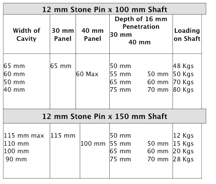
This Stoneclip support fixing is suitable for all surfaces (rough and rougher) and cavities from 40 mm to 115 mm and loads/ pin of 81 kgs/clip @30mm down to 12 kgs/ clip@ 115mm cavity .
This product has been tested by Stoneclip.com to perform to these specifications. We utilized Bostik Seal n Flex 1 as the filling and Bonding agent for our testing but far stronger more permanent but not flexible results are achievable using product such as Hilti HIT- RE 500. There are other products available but none, including the above are being put forward as the one to use.
The project specifier is the one to do this. The benefit derived from the use of the filling and bonding agent is in the type of substrate and the voids that may be in it, that the fixings are being installed into. This filling material helps in the installation into concrete filled blockwork, that can sometimes be bony and not a solid medium . The 12 mm shaft used is our Top & Bottom shaft fitted with the T & B head and the Intermediate 40 mm round head , both are attached using our shaft drilled system with the fixing a 6mm x 18 mm S S stud.
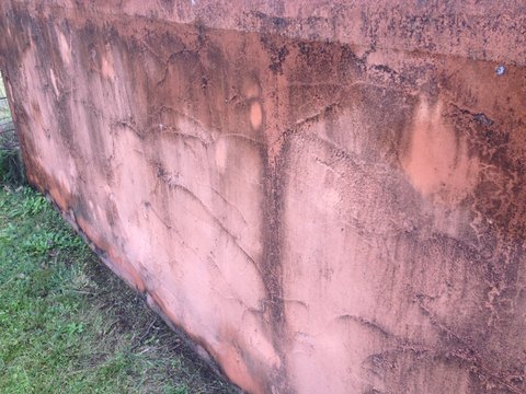
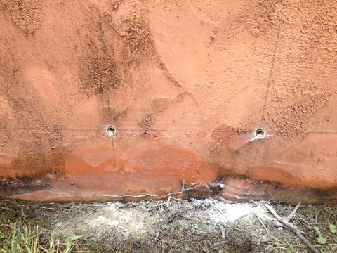
This rough plastered concrete block wall filled the bill for the type of substrate to test the product on . It is rough and parts as we drilled into it were found to be bony and only part filled
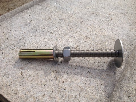
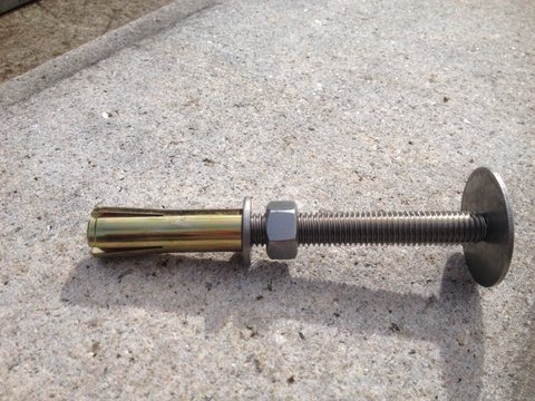
Showing a Stoneclip,12 mm StonePin with a 100 mm long shaft with a 40 mm removable front disc and a 12 mm drop in anchor (zinc-coated bit Stainless Steel available) attached to it .
Showing the above 12 mm StonePin with the internal steel plug driven home to show the expansion of the end that will happen in the penetration in the substrate .t
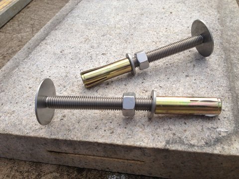
This is showing the above StonePin with the expanded end and another StonePin that has had the end of it filled with Bostik Seal n Flex 1 , prior to being installed in the 16 mm hole in the substrate and expanded prior to the shaft being fitted to it .
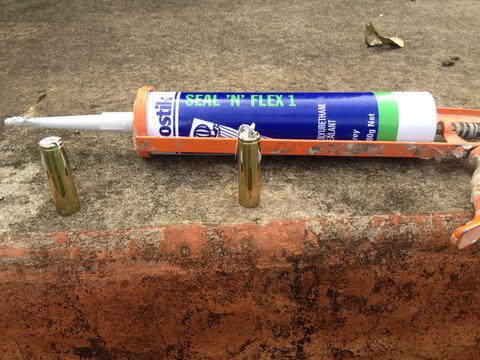
This shows the tube of BOSTIK Seal n Flex 1 and 2 of the 12 MM DROP IN ANCHORS that have been filled with the filler and bonding agent prior to being installed into the 2 x 16 mm x55 mm deep holes that have been drilled to accommodate them.
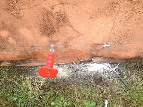
This shows the 2 DIA installed in their holes prior to the punch being used to drive the internal plug to expand the base in the hole.
This shows the punch that has been driven into the LHS anchor to a depth of a further 17 mm to drive the plug home. When doing this the filling and bonding agent has been transferred to fill the voids of space created when this action occurs and then if there is any voids in the substrate itself they are penetrated AND if there is none it is forced back around the outside of the DIA in the 16 mm drilled hole.
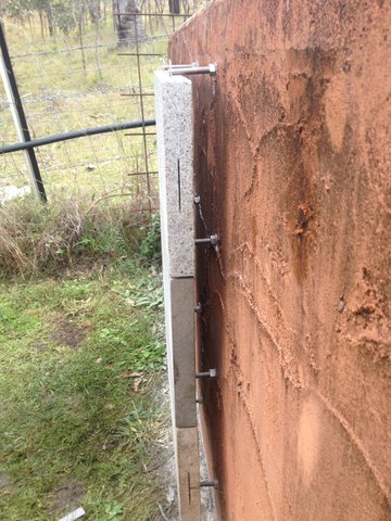
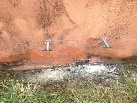
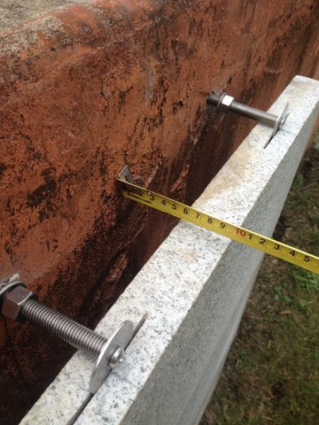
This shows the 2 shaft fixings installed into the DIA's with the attached Top & Bottom heads on them . Prior to installing the 12 mm shafts into the DIA, it has been filled to the front edge with the filler and bonding agent AND then as the shaft is installed to where it has to be to effect plumb on the panel the filler is further forced into the DIA and THEN WHEN IT IS IN THE RIGHT POSITION , THE NUT AND WASHER ARE THEN TIGHTENED BACK ONTO THE FACE OF THE SUBSTRATE . THE PENETRATION IS FULL AND THE EXCESS FILLER COMES OUT AROUND THE NUT .
This is the point where you effect the adjustment of the shaft or you should if necessary shorten the shaft at this point BEFORE INSTALLATION ,allowing the 25 mm of the shaft to be in the threaded front of the DIA .
At this point if you are able to establish the finished alignment of the panels you are able to drill the holes deeper into the substrate to effect the exact finished position of the front disc on the 12 mm shaft being installed ( by allowing that the shaft does screw into the Drop in Anchor by 25 mm when the bullet is driven home with the supplied driving pin) . Doing this eliminates any trimming of the shaft length.
The 10 mm StonePin is installed the same way but only screws into the DIA by 20mm.
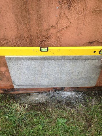
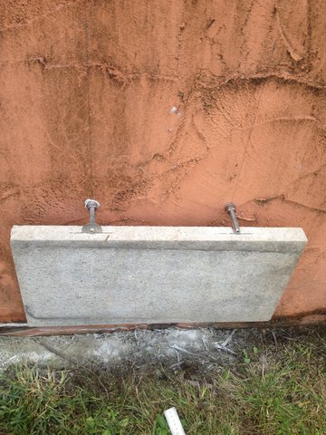
Shows the first 600 mm x300 mm x 40 mm = 20 kgs panel installed level on the first 2 X Top & Bottom brackets.
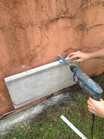
Shows drilling the 2 x 16 mm holes for the D I A 'S to restrain the top of this panel and support the underside of the panel above.By using the 1.5 mm shim as a rest and protector for the top of the panel, you are effecting a 3 mm space under the shaft . The joint width is effected by the installer to what he wants, on the underside of the above panel --the same way as with all Stoneclip fixings
This shows the LHS with the front disc installed onto the shaft and the RHS ready to have the disc attached.
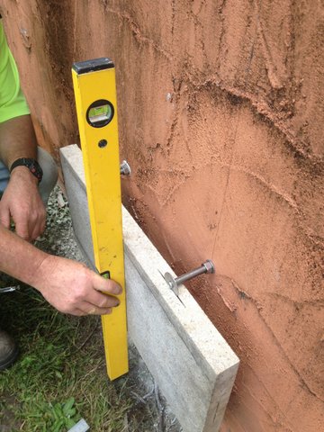
Showing the first panel installed plumb
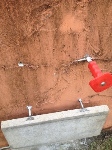
Showing the DIA being readied for the next panel, being expanded .
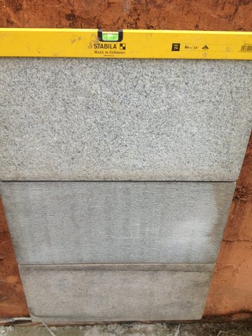
Showing 3 panels installed .
Showing the maximum cavity available with a 100 mm x 12 mm shaft using 40 mm thick panels. That is 65 mm using 30 mm panels.
Showing a side view of the panels and the rough substrate.