Support Clip Substructure
Using the Slimline Supportclip with an adjustable substructure the most common asked question by Architects is “do you have one”?
 |
 |
|||
|
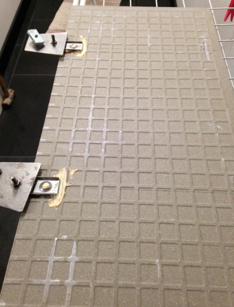
shows the back of a prepared tile with the Slimline Supportclip |
|
|
|
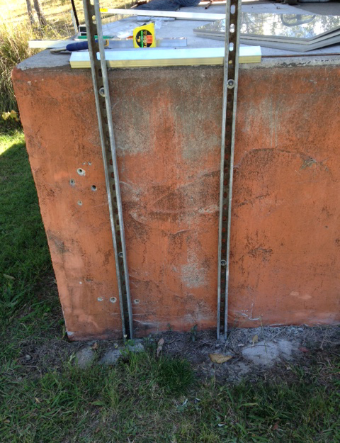
shows the installed 41 mm x 41 mm x 2.5mm thick wall channel that Whereas in the installation of the panels shown in photo 1 — these
|
 |
 |
|||
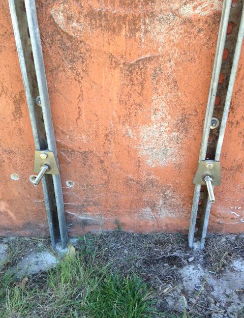
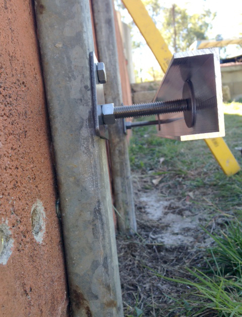
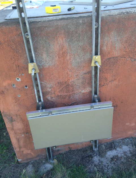
| shows the vertical channel with the 12 mm Trapezoid base plates with the 12 mm x 100 mm long shafts with the 6 mm x20 mm deep hole screw loosely into place to accept the bottom channel to fix onto them . The channel nuts securing them are 12 mm |
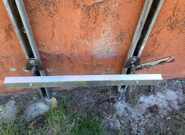
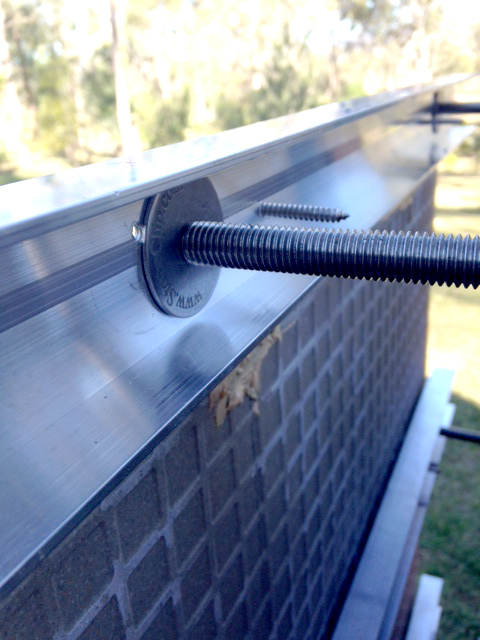
shows the Aluminum channel ( 50 mm x 25 mm deep x 3 mm thick ) fixed with the 6mm pan headed screw fixed through it into the end of the shaft .On the top of the channel can be seen the back washer ( 40 mm in diameter ), which has an insulation this nylon washer on one side of it to stop electrolysis between materials .This was also strengthens the front channel where it fits to the Stainless Steel shaft |
|||
 |
 |
|||
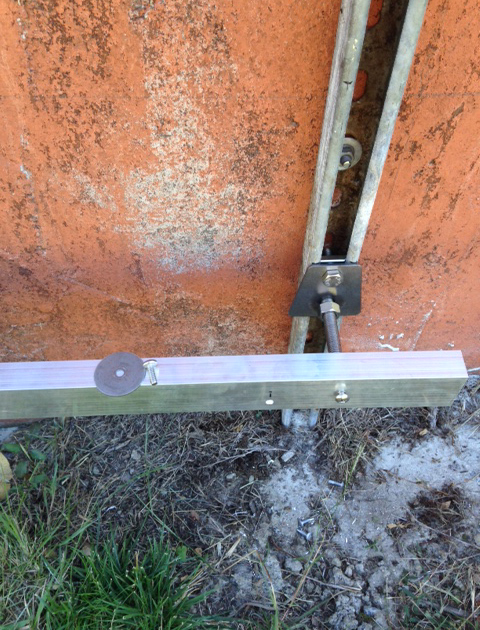
| shows the first channel being installed level onto the two shafts . At this point it is where you align for the right cavity you want to work to . The 41 mm deep channel allows you 35 mm adjustment inwards , so you are advised to start in relation to the plumb of the channel that you have erected . The threads are fully adjustable inwards and outwards by leaving the lock nuts loose till it exactly in place . To effect different cavity widths , you can shorten the shaft .In this case the overall cavity is 140 mm on the bottom and opens out to 150 mm on the top at 900 mm high |
shows a look into the back section of the channel after the
|
|||
 |
 |
|||
|
shows the bottom horizontal channel with the Slimline Supportclip |
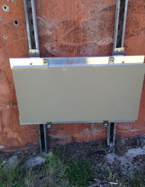
shows the first installed ceramic panel and where it will be secured to the horizontal channel through the top parts of the Supportclip (predrill these holes prior to securing with the 12 gauge screw ) |
|||
 |
 |
|||
| shows the next row of Trapezoid bases ( 2 off )installed in place ready to accept the next piece of channel to secure the next piece of ceramic tile to . These vertical channel would be all installed prior to the start of installation, to a layout to suit the panel lengths . The horizontal channel would be installed in lengths to suit the project , but both come in lengths of 6000 mm long . Placement of the vertical channel would be relevant to the size of the panels and their weight , but there is 2 needed / panel .Loadings for the system are in accordance with the loadings of the 12 mm StoneSub brackets minus the weight of the Aluminum channel / lin meter |
shows a back view of the installed bottom and top horizontal
|
|||
 |
 |
|||
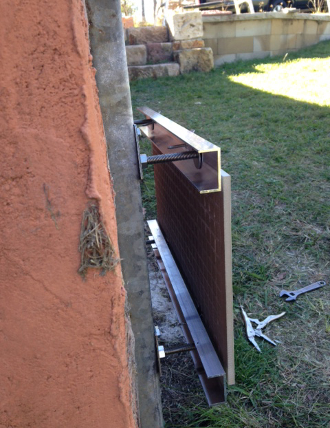
| shows the first 2 panels of ceramic installed . The bottom one is secured and the second one is in place to be screwed to the Aluminum channel .It shows the slight variance in horizontal height the channel can be installed at and still be in the right plane to accept fixing point of the Slimline Supportclip onto it .The bottom fixing point on the panel is where you install a silicone sealer in preference to an epoxy . This ensures movement of the panels in extreme situations instead of fracture if all rigidly held together |
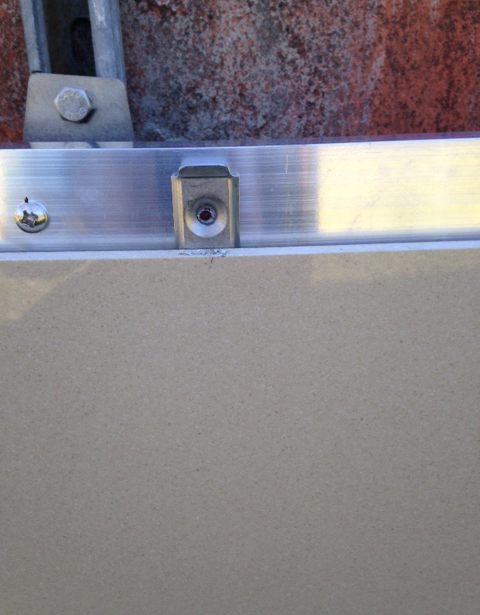
shows a view of the top of the fixing with the predrilled hole
|
|||
 |
 |
|||
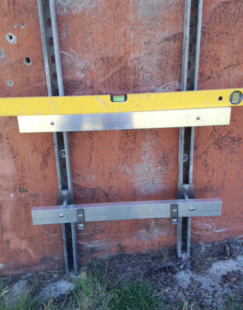
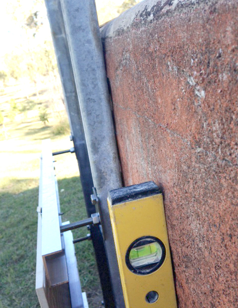
| shows the level against the substrate and it is leaning inwards 10 mm in 1000 mm high |
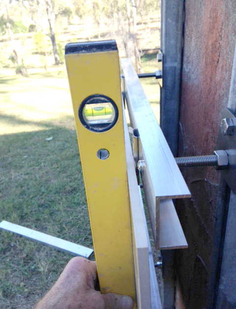
shows the level on the front face of the second installed panel
|
|||
 |
 |
|||
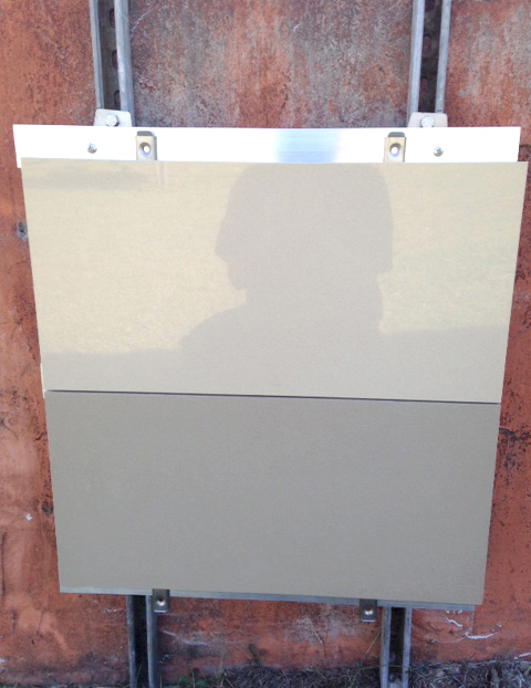
| shows the 3 panels installed and level and plumb . The top panel is yet to be secured with the screws |
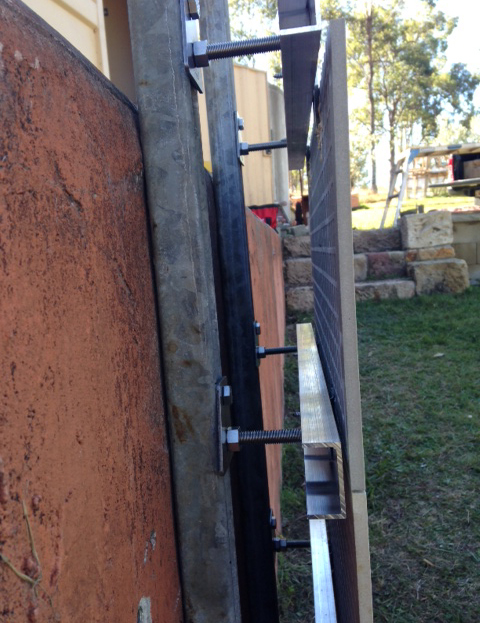
shows behind the finished façade . Showing the channel fitted onto the adjustable shafts and the fixings installed on the vertical channel |
|||
 |
 |
|||
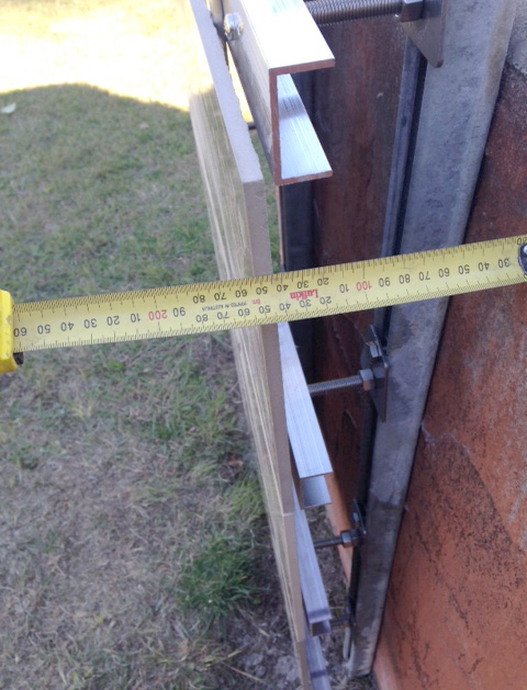
| shows the cavity achieved =150 mm , which is made up of 10 mm thick tile , 5 mm thick Slimline Supportclip , 3 mm thickness in horizontal channel,89 mm for the shaft and back plate to the face of the 41 mm vertical channel =total of 150 mm . The panel weight for the 600 mm x 300 mm x 10 mm thick panel is 5 kgs and the channel weight is .4 kgs/ 600 mm long piece , so the total loading is 2.7 kgs/ clip @shaft length of 75 mm |
shows a clean view behind the channel and the fixing screw from The positioning of the adjustable 12 mm brackets onto the vertical All of the panels would have their brackets installed prior to erection The load of the 50 mm x 25 mm x 3 mm thick channel is The cladding of the panels is covered by 2 separate sections — The wind load capacities are stated on the chart and if panels The costing of the lightweight substructure / m2 when The cost of of the lightweight substructure / m2 when
|